If the battery lights on your 2nd gen board, Mini S, Mini X, Boosted Plus or Stealth display the status code below, it indicates a connection issue between the battery and the motor controller. If you are in motion, the remote will beep continuously to alert you to this change in status. You will maintain braking control of the board but gradually lose the ability to accelerate.
Status Code
Standard Range Battery:
Power Button: Blinking Red
Bottom Battery Indicator: On Solid

Extended Range Battery:
Power Button: Flashing Yellow
Bottom Battery Indicator: 80, 60 and 40 percent light solid

Tools Required
4mm hex key
Connector grease DeoxIT D-Series D100L Mini-Brush Applicator.
Set of Boosted connector tools
The connection between the battery and motor controller may be re-established using the troubleshooting tips below: Video instructions here.
1. Remove the battery pack from your board. Using a 4mm hex tool, remove the 6 battery pack screws and wing plates holding the battery pack to the deck. Place them aside.

2. Lift the battery pack off the board. If present, unclip the the battery pack connector from around the metal wire connectors. Let it hang to the side.

3. Place the two plastic connector tools on either side of the metal connectors, making sure to fit the metal connector snugly into the curve of the tools. The ridge on the inside of the tools should sit along the outside of the metal rings, and the flat sides of the tools with the Boosted logos should be facing each other. WARNING: Do not use pliers to tighten or loosen the connectors as they will easily damage the threaded metal rings.


4. Now, squeeze the handles together and rotate the tools in opposite directions, until the metal wire connector comes loose. Remove the tools and then using your fingers undo to metal connectors until separated.

5. Under good lighting, check both sides of the battery connectors to make sure that there is no dust, debris, discoloration, wear, abrasion, or damage. If there is evidence of damage or deterioration, please call or contact us.

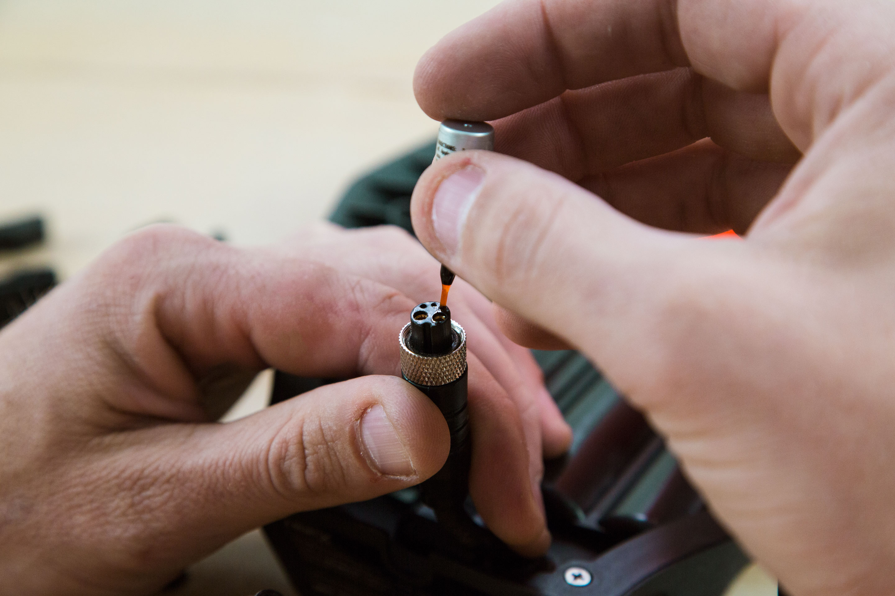
6. Locate the small vial of supplied connector lubricant. Using the brush inside the vial, thoroughly coat each of the 5 metal connector pins on one side and the connector pin holes on the other.


7. Connect and pull apart the two ends 3 or 4 times to make sure the connector lubricant thoroughly covers the pins. Then reconnect the two connector ends, making sure to push the two sides together securely. Next, hand tighten the metal connectors as securely as possible.

8. Place the two plastic connector tools on either side of the metal connectors, making sure to fit the metal connector snugly into the curve of the tools. The ridge on the inside of the tools should sit along the outside of the metal rings, and the flat sides of the tools with the Boosted logos should be facing each other. Now, squeeze the handles together and rotate the tools in opposite directions tightening until the connector is very snug. This could take a few rotations.

9. If present, you may remove the battery connector clip by snipping the zip tie that holds it to the wire.
10. Place the battery pack back onto the board.

11. Using the 6 bolts and wing plates from before, reattach the battery, making sure you’re not pinching anything. Make sure the battery sits flat against the deck before tightening all the screws. When you reattach, start with the middle bolt on both sides, in order to keep the battery from tilting to one side.

12. Power the board and remote back on. If you see a yellow light, that indicates the battery is not properly connected.